序言
上一个博文 中,我快速浏览了一遍tikz的基本语法,主要是 scope,path, 坐标,node 的 operation 和 option。
这些知识都是死的,看多少遍都是老样子,只有用起来才能将其串起来,变成活的。
我画了一个图之后基本上将这些知识串的差不多了,嗯。
我的workflow
我选择独立编译tikz的代码为pdf,然后作为图片加入主tex。
有人只将tikz的代码部分(不包含preamble)input到主tex,但我怕这么搞会拖慢编译速度,就放弃了,反正图片一般不怎么变。
还有人使用standalone class编译tikz代码,然后在主tex中使用standalone package载入tikz代码文件(包含preamble,但主tex不需要加入对应的preamble),这样tikz图片的代码既可以独立编译,也可以原封不动的载入到主tex,但我还是嫌弃它可能拖慢编译速度,还是折衷了一下:
仅使用standalone class编译tikz代码为pdf。
注:tikz的图片代码使用啥文档class都行,如ctexart都行,没必要非得用 standalone class。
我把主要部分贴出来,用于我们调用了xeCJK库,因此支持中文:
\documentclass[border=0pt]{standalone}
\usepackage{tikz}
\usetikzlibrary{calc,positioning,shadows.blur,fit,decorations.text,arrows,arrows.meta,backgrounds}
\usepackage{pifont}
\renewcommand{\labelitemi}{\ding{112}}
\usepackage{xeCJK}
\setCJKmainfont{SimSun}

\begin{document}

\begin{tikzpicture}
Youre tikz code here.
\end{tikzpicture}

\end{document}
模型结构图
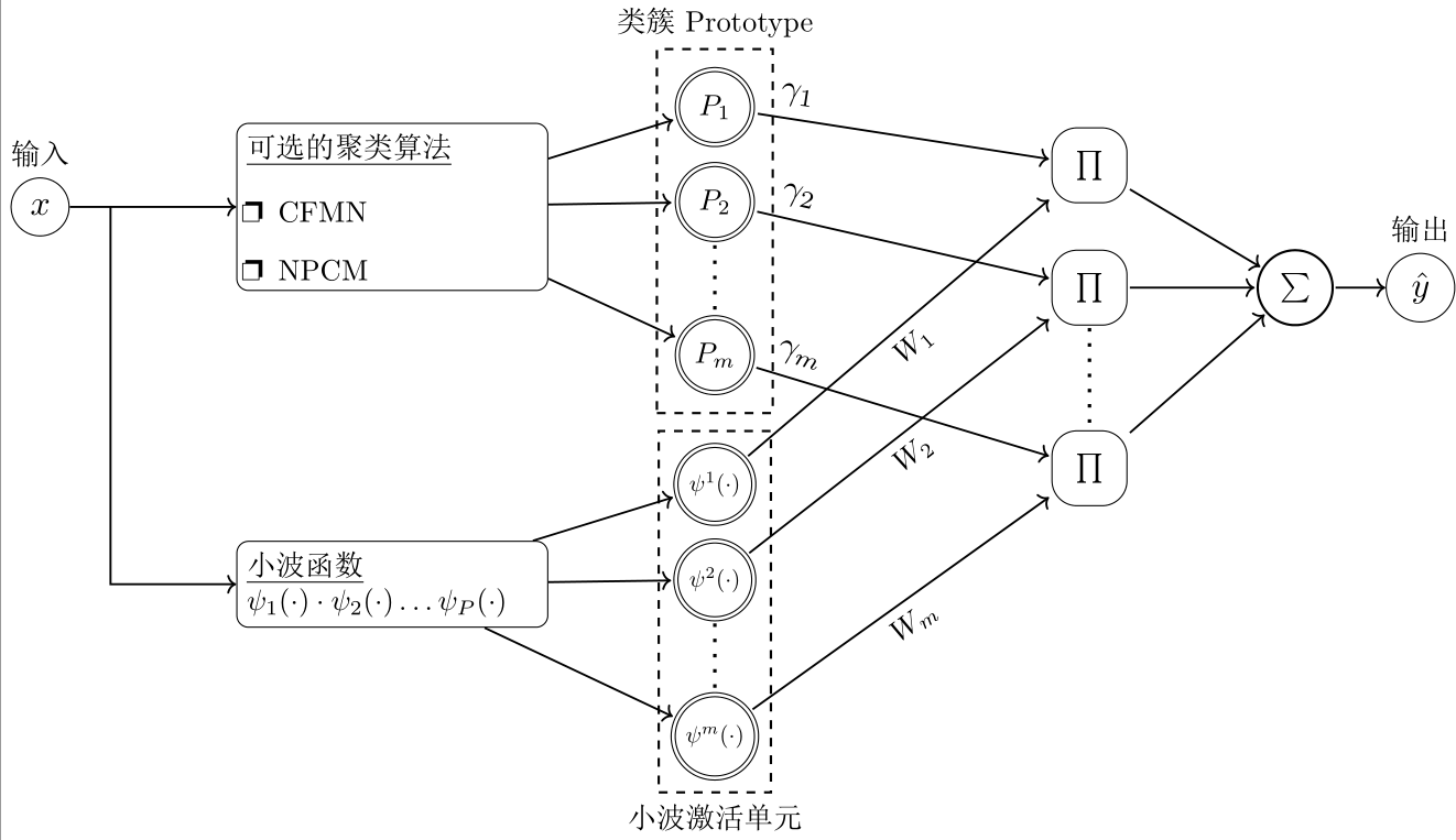
注意事项:
- node中放入多行文本,或很长的文本的时候若提示编译问题,可尝试设置
text width。 - node之间可以作为坐标进行连接,如果出现不正常的效果,例如连接两个node的时候希望在连线上设置新node,这时候新node的内容可能出现在坐标原点,而非我们期望的地方,这时候应该尝试用 edge,换言之:node之间的连接最靠谱的还是edge operation
用到的知识点:
- 构建自己的style
- 设置node的各种属性,如:
- outer sep在需要画箭头的时候很有用,这样箭头就不会紧挨着node了:
- 直接对一个node 设置scale,它就会放大缩小,很直观
- 将node设为double,就是双边缘,通过double distance选项可以方便设置双边缘的间隔。
- rounded corners属性,将node的corner设为平滑的过渡
- 构建node的同时使用label选项,可以方便为这个node设置标签
- 使用positioning库之后,就可以方便使用above,below = of 等,很方便
- 使用calc库之后就可以方便计算各种坐标了,如Partway Modifiers就很有用,可以方便取两个坐标中间的某一个地方的点。 如:
\draw [arrow_line] ($(x_input)!0.2!(clustering_structure)$) |- (wavelet_func); - 坐标计算除了上面的partway的方式,还可以:
($(clustering_structure.east) +(6.5cm,0.5cm)$) - backgrounds 允许我们将东西画在背景上,如
\begin{scope}[on background layer]
代码:
\begin{tikzpicture}[every node/.style={},
prototype/.style={draw, circle,double,minimum size= 0.9 cm,outer sep=2 pt,double distance=1pt},
wavelet/.style={draw, circle,double,minimum size= 0.9 cm,outer sep=2 pt,scale =0.8,double distance=1pt},
pi_style/.style={draw, minimum size= 0.9 cm,outer sep=1 pt, rounded corners=0.3cm},
arrow_line/.style={->,line width=0.7pt},
box/.style={text width =3.5cm, draw, rounded corners}]

//input
\node [circle, draw,scale=1.2, label=above:输入] (x_input) {$x$};

//Clustering Module
\node  [right =2cm of x_input, box] (clustering_structure) {\underline{可选的聚类算法} \\
        \begin{itemize}
        \setlength{\itemindent} {-.5cm}
        \item CFMN
        \item NPCM
        \end{itemize}
        };
// connect input to     Clustering Module
\draw [arrow_line] (x_input) -- (clustering_structure);

// Prototype Layer
\node at ( $(clustering_structure.east)+(2cm,1.2cm)$) [prototype] (p1) {$P_1$};
\draw [arrow_line] (clustering_structure) -- (p1);

\node [below =0.1cm of p1,prototype] (p2) {$P_2$};
\draw [arrow_line] (clustering_structure) -- (p2);

\node [below  = 0.8cm of p2,prototype] (pm) {$P_m$};
\draw [arrow_line] (clustering_structure) -- (pm);

\draw[loosely dotted,line width =1.2 pt] (p2) edge (pm);

// draw prototype layer text
\begin{scope}[on background layer]
  \node [fit = (p1) (p2) (pm), dashed,draw,  thick, label=above:类簇 Prototype, inner sep = 5pt] {};
\end{scope}

//Wavelet Module
\node [below = 3cm of clustering_structure, box] (wavelet_func) {\underline{小波函数} \\
$\psi_1(\cdot) \cdot \psi_2(\cdot) \ldots \psi_P(\cdot)$};

//Wavelet Layer
\node at ( $(wavelet_func.east)+(2cm,1.2cm)$) [wavelet] (w1) {$\psi^1(\cdot)$};
\draw [arrow_line] (wavelet_func) -- (w1);

\node [below =0.1cm of w1,wavelet] (w2) {$\psi^2(\cdot)$};
\draw [arrow_line] (wavelet_func) -- (w2);

\node [below  = 0.8cm of w2,wavelet] (wm) {$\psi^m(\cdot)$};
\draw [arrow_line] (wavelet_func) -- (wm);

\draw[loosely dotted,line width =1.2 pt] (w2) edge (wm);

// draw wavelet layer text
\begin{scope}[on background layer]
  \node [fit = (w1) (w2) (wm), dashed,draw,  thick, label=below:小波激活单元] {};
\end{scope}

// connect input to wavelet
\draw [arrow_line] ($(x_input)!0.2!(clustering_structure)$) |- (wavelet_func);

//Product Layer
\node at ($(clustering_structure.east) +(6.5cm,0.5cm)$) [pi_style] (pr1) {$\prod$};
\node [below = 0.5cm of pr1, pi_style] (pr2) {$\prod$};
\node [below = 1.2cm of pr2, pi_style] (prm) {$\prod$};

//connect  Prototype Layer and Wavelet Layer to the Product Layer
\path [arrow_line] (p1) edge node [very near start,above,sloped,scale=1.2] {$\gamma_1$} (pr1);
\path [arrow_line] (p2) edge node [very near start,above,sloped,scale=1.2] {$\gamma_2$} (pr2);
\path [arrow_line] (pm) edge node [very near start,above,sloped,scale=1.2] {$\gamma_m$} (prm);
\draw[loosely dotted,line width =1.2 pt] (pr2) edge (prm);

\path [arrow_line] (w1) edge node [below,sloped] {$W_1$} (pr1);
\path [arrow_line] (w2) edge node [below,sloped] {$W_2$} (pr2);
\path [arrow_line] (wm) edge node [below,sloped] {$W_m$} (prm);

// sum layer
\node  [right = 1.5cm of pr2,minimum size=0.9cm,draw,thick,circle,outer sep=1 pt] (sum_layer) {$\sum$};
// connect product layer to sum layer
\path  [arrow_line] (pr1) edge (sum_layer);
\path  [arrow_line] (pr2) edge (sum_layer);
\path  [arrow_line] (prm) edge (sum_layer);

//output
\node [right = 0.6cm of sum_layer,circle, draw,scale=1.2, label=above:输出] (y_output) {$\hat{y}$};
//connect
\path  [arrow_line] (sum_layer) edge (y_output);


\end{tikzpicture}